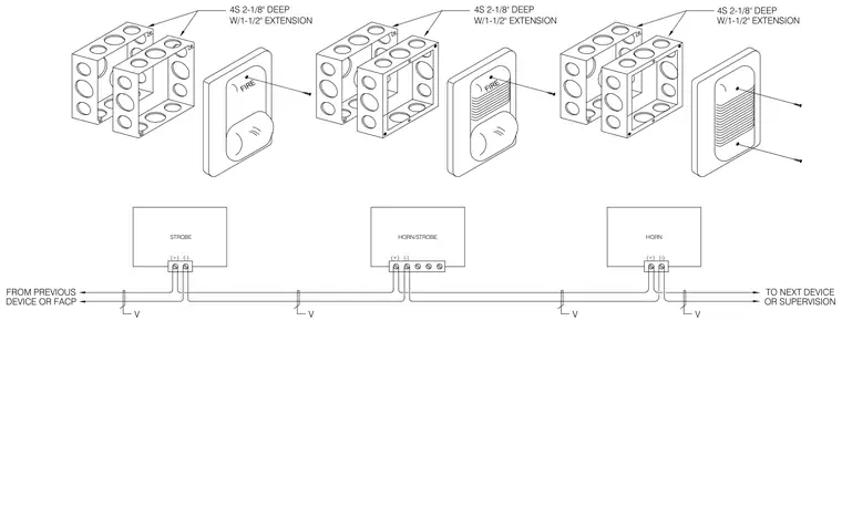
Fire alarm notification appliances including strobes, horns, and horn-strobes are installed in 4S two-and-one-eighth-inch deep square electrical boxes fitted with one-and-one-half-inch extensions. The electrical wiring runs continuously from the previous device or fire alarm control panel, tapping into positive and negative terminal screws on each notification device before continuing to the next device or supervision module. Circuit wiring includes voltage supervision drops at each device location. Faceplates secure to the backbox assemblies using mounting screws.
DEVICE OR FACP FROM PREVIOUS V (+) (-) STROBE V FIRE 4S 2-1/8" DEEP W/1-1/2" EXTENSION HORN/STROBE (+) (-) HORN (+) V V (-) TO NEXT DEVICE OR SUPERVISION W/1-1/2" EXTENSION 4S 2-1/8" DEEP W/1-1/2" EXTENSION FIRE 4S 2-1/8" DEEP
Members view this detail in full resolution, download the CAD files (SVG, PDF), and can adapt it in the built-in CAD editor — export DXF, DWG, or PDF.
Start membership