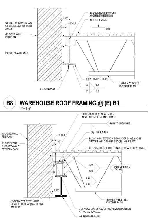
A roof framing connection at an existing concrete wall supports an open web steel joist and a wide-flange beam. The assembly incorporates an HSS 10x4x3/8 member cut to fit snug below the seat angle, supported by three-quarter-inch shim plates extending three inches beyond the open web joist seat. Five-sixteenth-inch and quarter-inch fillet welds secure the steel components, while deck edge support angles and one-and-a-half-inch B-decking complete the roof assembly.
(E) CONC. WALL PER PLAN (E) 1 1/2" B DECK 12 5/16 (E) OPEN WEB STEEL JOIST PER PLAN (E) WF BM PER PLAN 4 1/2" 2" CLR CUT (E) BEAM FLANGE 1/4 4-8 1/4 4-8 L3x3x1/4 CONT CUT (E) HORIZONTAL LEG OF DECK EDGE SUPPORT ANGLE (E) DECK EDGE SUPPORT ANGLE BETWEEN OWJ (E) CONC. WALL PER PLAN (E) 1 1/2" B DECK (E) OPEN WEB STEEL JOIST PER PLAN (E) OPEN WEB STEEL JOIST SEATED CONN. W/ (4) ADHESIVE ANCHORS 2" CLR HSS 10x4x3/8 CUT TO FIT SNUG BELOW (E) SEAT ANGLE PL 3/4" SHIM, EXTEND 3" BEYOND OPEN WEB JOIST SEAT ES. WELD TO HSS AND (E) ANGLE SEAT. 1 1/2" CUT END OF JOIST SEAT AFTER INSALLATION OF BM AND SHIMS CUT HORZ. LEG OF ANGLE AND REMOVE PORTION ATTACHED TO WALL. WF BEAM PER PLAN 5/16 5/16 5 1/2" (E) DECK EDGE SUPPORT ANGLE BETWEEN OWSJ SHIM TO ANGLE LEG 5/16 5/16 ENDS OF SHIM & L TO HSS 1" = 1'-0" B8 WAREHOUSE ROOF FRAMING @ (E) B1
Members view this detail in full resolution, download the CAD files (SVG, PDF), and can adapt it in the built-in CAD editor — export DXF, DWG, or PDF.
Start membership