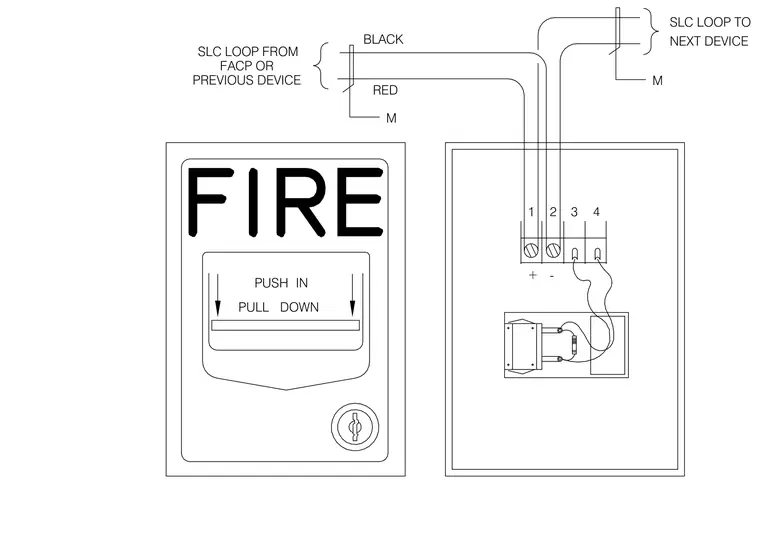
The signaling line circuit loop connects from the fire alarm control panel or a previous device to terminals one and two of the manual pull station, utilizing black and red conductors marked with module designations. Terminals three and four route the loop onward to the next device in the system. The front faceplate of the device features prominent fire lettering and instructions to push in and pull down on the activation bar.
FACP OR + PREVIOUS DEVICE PUSH PULL DOWN IN RED M 1 - 3 2 4 M SLC LOOP FROM BLACK SLC LOOP TO NEXT DEVICE
Members view this detail in full resolution, download the CAD files (SVG, PDF), and can adapt it in the built-in CAD editor — export DXF, DWG, or PDF.
Start membership