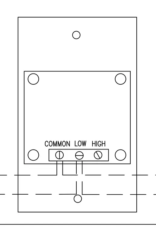
This diagram details the terminal connections for a pressure switch used in fire protection systems. The terminal block features three clearly labeled connection points for common, low, and high signals. Wiring feeds into the lower terminals through designated conduit or cable pathways. Mounting holes are positioned around the perimeter of the switch assembly for secure attachment.
Members view this detail in full resolution, download the CAD files (SVG, PDF), and can adapt it in the built-in CAD editor — export DXF, DWG, or PDF.
Start membership