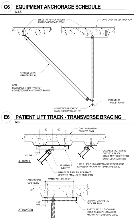
Transverse bracing and vertical hanger assembly for a patient lift track suspended from a concrete over metal deck slab. The vertical hanger consists of a threaded rod connected to a manufacturer-provided bracket and a 1 5/8-inch by 1 5/8-inch by 12-gauge channel strut anchored to the concrete deck using two 5/8-inch diameter expansion anchors with a 4-inch effective embedment. The transverse brace uses a matching channel strut connected via an adjustable hinge, oriented parallel to the deck span. The offset from the deck centerline and maximum dimensions for standard strut placement are clearly called out, with provisions for centering under the deck low flute.
AT BRACE AT HANGER CONC. OVER METAL DECK PER PLAN ADJUSTABLE HINGE TYP. EQ EQ 1 5/8" X 1 5/8" X 12GA CHANNEL STRUT W/ (2) 5/8"Ø EXPANSION ANCHOR W/ 4" EFFECTIVE EMBED 1 1/2" TYP. BRACE PER PLAN, SIM. PER BRACE ORIENTED PARALLEL TO DECK SPAN 1 5/8" X 1 5/8" X 12 GACHANNEL STRUT W/ (2) 5/8"Ø EXPANSION ANCHOR W/ 4" EFFECTIVE EMBED TYP 1 1/2" (N) CONC. OVER METAL DECK PER PLAN CL OF DECK 1" OFFSET FROM CHANNEL STRUT MAY BE OMITTED IF BRACE ATTACHMENT IS CENTERED UNDER DECK LOW FLUTE 11" MAX WITH STD STRUT CONC OVER MTL DECK PER PLAN PATIENT LIFT TRACK BY MANUF CONNECTION BRACKET AT HANGER ROD BY MANUF, TYP CHANNEL STRUT BRACE PER PLAN SEE DETAIL F6/- FOR HANGER & BRACE ANCHORAGE DETAIL NOTE: SEE DETAIL F4/- FOR TYP STRUT CONNECTION INFORMATION NOT SHOWN N.T.S. C6 EQUIPMENT ANCHORAGE SCHEDULE NTS E6 PATIENT LIFT TRACK - TRANSVERSE BRACING
Members view this detail in full resolution, download the CAD files (SVG, PDF), and can adapt it in the built-in CAD editor — export DXF, DWG, or PDF.
Start membership