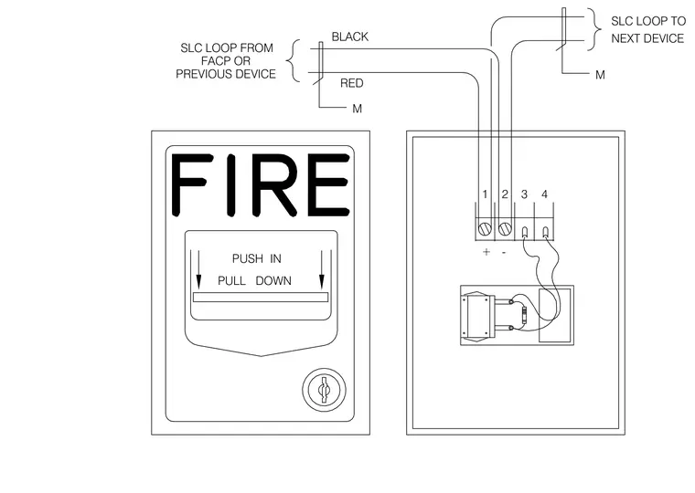
Wiring diagram for a fire alarm manual pull station showing terminal block connections for the signaling line circuit loop. The black SLC loop conductor connects to terminal one with positive polarity, while the red conductor connects to terminal two with negative polarity. The circuit continues from terminals three and four to the next device on the loop. A monitor module designation is indicated on the circuit lines entering and leaving the station.
FACP OR + PREVIOUS DEVICE PUSH PULL DOWN IN RED M 1 - 3 2 4 M SLC LOOP FROM BLACK SLC LOOP TO NEXT DEVICE
Members view this detail in full resolution, download the CAD files (SVG, PDF), and can adapt it in the built-in CAD editor — export DXF, DWG, or PDF.
Start membership