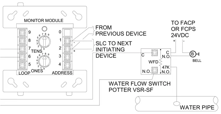
A Potter VSR-SF water flow switch connects to a monitor module with address dials set via tens and ones rotaries, linking the water pipe sensor to the signaling line circuit. The signaling line circuit runs from the previous device through the module terminals to the next initiating device, powered by twenty-four volts direct current from the fire alarm control panel or fire alarm control power supply. A forty-seven kilohm end-of-line resistor is wired across the normally open and common contacts of the water flow switch loop. A remote bell notification appliance ties into the system circuit for audible alarm signaling upon water flow detection.
LOOP 2 3 1 0 2 5 4 1 0 7 9 8 6 + + - 5 4 3 8 9 7 6 - MONITOR MODULE BELL 9 8 7 6 5 0 1 2 3 4 ADDRESS ONES TENS WATER PIPE WATER FLOW SWITCH POTTER VSR-SF TO FACP OR FCPS 24VDC FROM PREVIOUS DEVICE SLC TO NEXT INITIATING DEVICE WFD N.O. 47K C C N.O. N.O. B
Members view this detail in full resolution, download the CAD files (SVG, PDF), and can adapt it in the built-in CAD editor — export DXF, DWG, or PDF.
Start membership