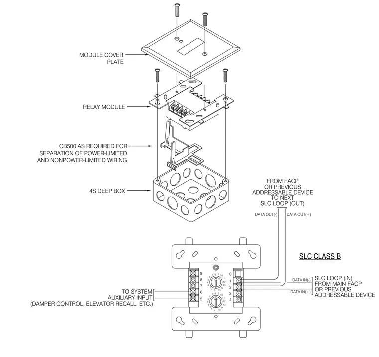
An addressable relay module mounts within a deep square electrical box and is secured with machine screws beneath a matching module cover plate. A CB500 barrier is included as required for the physical separation of power-limited and nonpower-limited wiring. Signal line circuit Class B wiring connects from the main fire alarm control panel or a previous addressable device to the module terminals and loops out to the next device. Additional wiring extends from the relay contacts to system auxiliary inputs for functions such as damper control and elevator recall.
MODULE COVER PLATE RELAY MODULE CB500 AS REQUIRED FOR SEPARATION OF POWER-LIMITED AND NONPOWER-LIMITED WIRING 4S DEEP BOX 3 13 2 0 1 14 15 SLC CLASS B FROM MAIN FACP ADDRESSABLE DEVICE OR PREVIOUS SLC LOOP (IN) TO SYSTEM AUXILIARY INPUT 7 9 7 6 5 8 NC C NC NO 6 8 7 0 1 2 3 4 5 4 6 5 C 8 TO NEXT OR PREVIOUS SLC LOOP (OUT) ADDRESSABLE DEVICE 0 10 3 2 4 11 11 9 15 10 14 13 12 12 1 NO 9 DATA OUT(-) DATA IN(+) DATA IN(-) DATA OUT(+) FROM FACP (DAMPER CONTROL, ELEVATOR RECALL, ETC.)
Members view this detail in full resolution, download the CAD files (SVG, PDF), and can adapt it in the built-in CAD editor — export DXF, DWG, or PDF.
Start membership