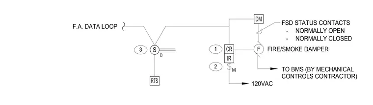
This wiring and control diagram outlines the interconnection between a fire alarm data loop, a remote test station, control relays, and a motorized fire and smoke damper. Power is supplied via a 120VAC connection routed through interface and control relays. The fire and smoke damper provides normally open and normally closed status contacts routed to the building management system by the mechanical controls contractor.
S F M D RTS CR IR DM 3 1 2 120VAC F.A. DATA LOOP FIRE/SMOKE DAMPER FSD STATUS CONTACTS - NORMALLY OPEN - NORMALLY CLOSED TO BMS (BY MECHANICAL CONTROLS CONTRACTOR)
Members view this detail in full resolution, download the CAD files (SVG, PDF), and can adapt it in the built-in CAD editor — export DXF, DWG, or PDF.
Start membership