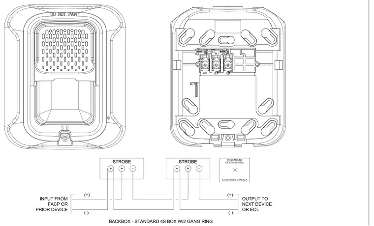
Fire alarm notification appliance wiring diagram showing polarity connections for wall-mounted strobes. The schematic details power input from the fire alarm control panel or prior device, loop continuation to the next device or end-of-line resistor, and terminal block screw connections. A standard square four-inch electrical backbox with a two-gang ring is specified for mounting. The device housing indicates a do-not-paint requirement.
OUTPUT TO NEXT DEVICE OR EOL (-) (+) INPUT FROM FACP OR PRIOR DEVICE (-) (+) + + - STROBE + + - STROBE WALL MOUNT DEVICE SYMBOL XX DENOTES CANDELA BACKBOX - STANDARD 4S BOX W/2 GANG RING
Members view this detail in full resolution, download the CAD files (SVG, PDF), and can adapt it in the built-in CAD editor — export DXF, DWG, or PDF.
Start membership