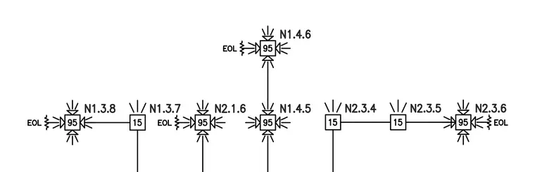
This fire alarm system schematic outlines a series of interconnected addressable devices with module numbers such as N1.4.6, N1.3.8, N1.3.7, N2.1.6, N1.4.5, N2.3.4, N2.3.5, and N2.3.6. Square symbols numbered 95 and 15 represent specific notification or control appliances within the loop. End-of-line EOL resistors are designated at circuit terminations to supervise wiring integrity. Lines indicate wiring paths connecting the notification appliance circuits.
Members view this detail in full resolution, download the CAD files (SVG, PDF), and can adapt it in the built-in CAD editor — export DXF, DWG, or PDF.
Start membership