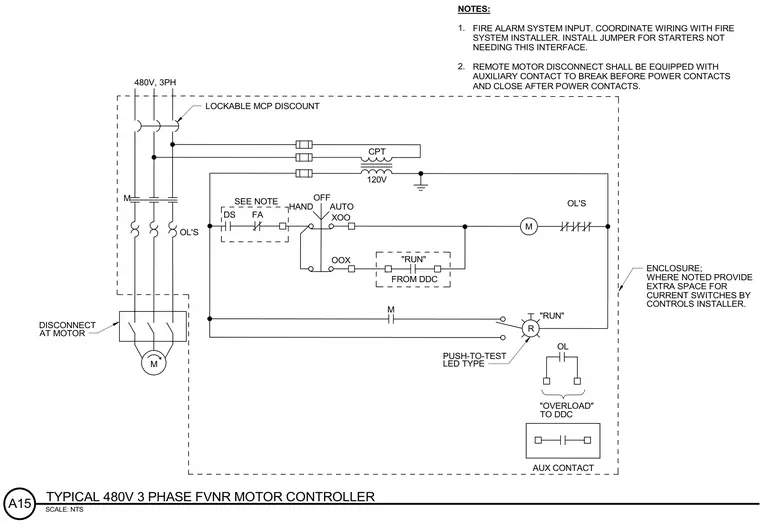
This electrical schematic details a typical 480V three-phase full voltage non-reversing motor controller layout. A lockable motor circuit protector precedes the main contactor and overload relays for circuit protection. A control power transformer steps down the voltage to 120V for the control circuit, which includes a hand-off-auto selector switch and run status indicators. Integration with the direct digital control system and fire alarm system is provided via auxiliary contacts and interlock wiring. A remote motor disconnect with early-break auxiliary contacts connects downstream, while extra space is allocated within the enclosure for current switches.
OL'S M 120V M CPT OL'S 480V, 3PH M M R AUTO OFF HAND XOO OOX "RUN" FROM DDC OL FA SEE NOTE "RUN" NOTES: "OVERLOAD" TO DDC FIRE ALARM SYSTEM INPUT. COORDINATE WIRING WITH FIRE SYSTEM INSTALLER. INSTALL JUMPER FOR STARTERS NOT NEEDING THIS INTERFACE. REMOTE MOTOR DISCONNECT SHALL BE EQUIPPED WITH AUXILIARY CONTACT TO BREAK BEFORE POWER CONTACTS AND CLOSE AFTER POWER CONTACTS. LOCKABLE MCP DISCOUNT PUSH-TO-TEST LED TYPE DISCONNECT AT MOTOR ENCLOSURE; WHERE NOTED PROVIDE EXTRA SPACE FOR CURRENT SWITCHES BY CONTROLS INSTALLER. 1. 2. AUX CONTACT DS SCALE: NTS A15 TYPICAL 480V 3 PHASE FVNR MOTOR CONTROLLER
Members view this detail in full resolution, download the CAD files (SVG, PDF), and can adapt it in the built-in CAD editor — export DXF, DWG, or PDF.
Start membership