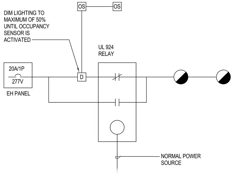
An emergency lighting control diagram connects a 20-amp single-pole 277-volt circuit from an emergency lighting panel to a dimmer and a UL 924 emergency relay. Two occupancy sensors link to the control module, limiting lighting output to a maximum of 50 percent until an occupancy sensor activates. A normal power source bypasses the relay contacts to feed downstream lighting fixtures under standard operating conditions.
D OS OS 20A/1P 277V UL 924 RELAY EH PANEL NORMAL POWER SOURCE DIM LIGHTING TO MAXIMUM OF 50% UNTIL OCCUPANCY SENSOR IS ACTIVATED
Members view this detail in full resolution, download the CAD files (SVG, PDF), and can adapt it in the built-in CAD editor — export DXF, DWG, or PDF.
Start membership