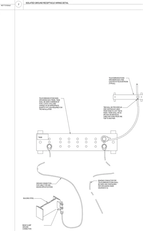
Telecommunications main grounding bus is sized a minimum of 4 inches wide by 1/4 inch high by 20 inches long and includes an appropriate quantity of lugs for the installation. The telecommunications backbone bonding conductor is provided as one continuous cable from the main grounding bus to the last telecommunications grounding bus in the riser with no splices or individual cable sections. A typical telecommunications grounding bus is located in the telecom room. The ground connection to building steel uses a beam clamp ground connection.
NOT TO SCALE TMGB TBB SHALL BE PROVIDED AS ONE CONTINUOUS CABLE FROM TMGB TO LAST TGB IN RISER. THERE SHALL BE NO SPLICES OR INDIVIDUAL CABLE SECTIONS FROM ONE TGB TO ANOTHER. TELECOMMUNICATIONS MAIN GROUNDING BUS (TMGB). TMGB SHALL BE SIZED A MINIMUM OF 4"(W) x 1/4"(H) x 20"(L) AND CONSIST OF AN APPROPRIATE QUANTITY OF LUGS REQUIRED FOR THE INSTALLATION GROUND CONNECTION FOR CABLE TYPE SEE DESIGN SPECIFICATIONS BONDING CONDUCTOR FOR TELECOMMUNICATIONS SHALL BE SIZED AND CONFIGURED PER GROUNDING RISER DIAGRAM E7.02 TELECOMMUNICATIONS GROUNDING BUS (TGB) LOCATED IN TELECOM ROOM. (TYPICAL) BEAM CLAMP GROUND CONNECTION BUILDING STEEL 2 ISOLATED GROUND RECEPTACLE WIRING DETAIL
Members view this detail in full resolution, download the CAD files (SVG, PDF), and can adapt it in the built-in CAD editor — export DXF, DWG, or PDF.
Start membership