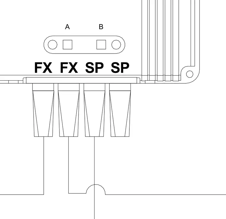
The telecommunications assembly features labeled FX and SP ports alongside designation markers A and B. Cables terminate into vertically aligned connector boots extending from the panel housing. The arrangement provides structured cable routing for network infrastructure connections.
Members view this detail in full resolution, download the CAD files (SVG, PDF), and can adapt it in the built-in CAD editor — export DXF, DWG, or PDF.
Start membership