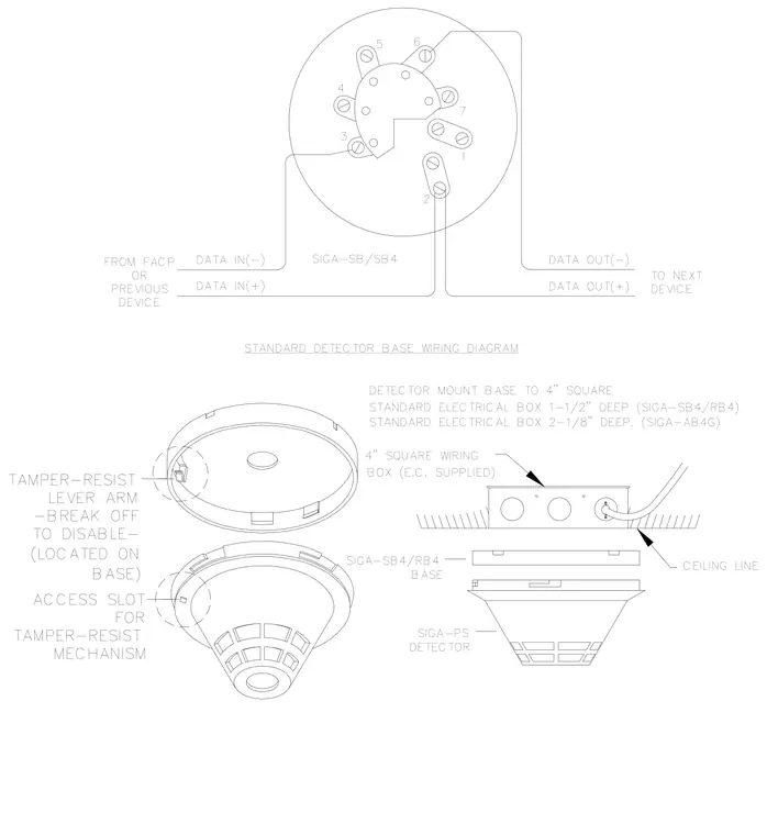
Installation and wiring configuration for a standard smoke or heat detector mounted to a ceiling. The assembly connects to a four-inch square electrical box, either one-and-one-half inches or two-and-one-eighth inches deep, supplied by the electrical contractor behind the ceiling line. The SIGA-SB4 or RB4 detector base secures to the box and interfaces with the detector unit. Wiring connections route data in and data out terminals from the fire alarm control panel or previous device to the next device in the loop. A tamper-resistant lever arm located on the base includes a break-off feature to disable the lock alongside an access slot for the mechanism.
DETECTOR MOUNT BASE TO 4" SQUARE STANDARD ELECTRICAL BOX 1-1/2" DEEP (SIGA-SB4/RB4) 5 DATA IN(-) DATA IN(+) DEVICE PREVIOUS OR FROM FACP 3 4 2 DATA OUT(-) DATA OUT(+) TO NEXT DEVICE 1 7 6 SIGA-SB/SB4 STANDARD DETECTOR BASE WIRING DIAGRAM BOX (E.C. SUPPLIED) SIGA-PS DETECTOR SIGA-SB4/RB4 BASE 4" SQUARE WIRING CEILING LINE STANDARD ELECTRICAL BOX 2-1/8" DEEP. (SIGA-AB4G) TAMPER-RESIST LEVER ARM -BREAK OFF TO DISABLE- (LOCATED ON BASE) ACCESS SLOT FOR TAMPER-RESIST MECHANISM
Members view this detail in full resolution, download the CAD files (SVG, PDF), and can adapt it in the built-in CAD editor — export DXF, DWG, or PDF.
Start membership