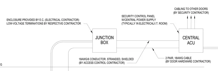
The security system connection layout coordinates low-voltage wiring between a junction box and a central access control unit located in the electrical or I.T. room. The junction box features a ceiling enclosure provided by the electrical contractor with low-voltage terminations handled by the respective trade. Cabling routed between the junction box and the central ACU consists of an eighteen-gauge, six-conductor stranded and shielded cable installed by the access control contractor. A two-pair, eighteen-gauge cable provided by the door hardware contractor runs from the junction box to the doors. Additional cabling extends from the central security control unit to other doors.
CEILING ENCLOSURE PROVIDED BY E.C. (ELECTRICAL CONTRACTOR) LOW-VOLTAGE TERMINATIONS BY RESPECTIVE CONTRACTOR JUNCTION BOX CENTRAL ACU W/CENTRAL POWER SUPPLY (TYPICALLY IN ELECTRICAL/I.T. ROOM) 2 PAIR, 18AWG CABLE (BY DOOR HARDWARE CONTRACTOR) CABLING TO OTHER DOORS (BY SECURITY CONTRACTOR) 18AWG/6 CONDUCTOR. STRANDED, SHIELDED (BY ACCESS CONTROL CONTRACTOR) SECURITY CONTROL PANEL
Members view this detail in full resolution, download the CAD files (SVG, PDF), and can adapt it in the built-in CAD editor — export DXF, DWG, or PDF.
Start membership