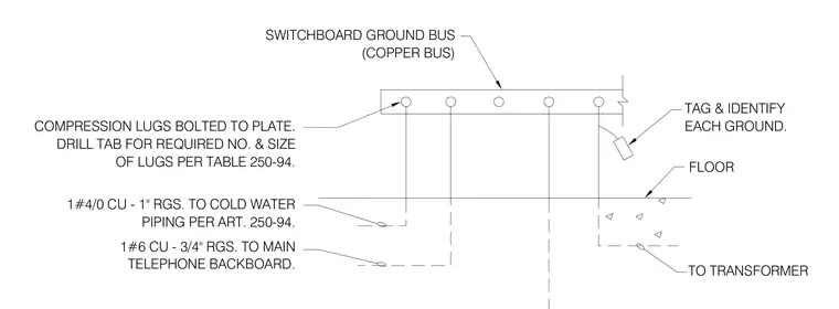
A copper switchboard ground bus is connected to compression lugs bolted to the plate, with the tab drilled for the required number and size of lugs per Table 250-94. Conductors include 1#4/0 copper in 1-inch rigid galvanized steel conduit routed to cold water piping per Article 250-94, and 1#6 copper in 3/4-inch rigid galvanized steel conduit routed to the main telephone backboard. Additional connections route to the transformer through the floor, with each ground tagged and identified.
1#4/0 CU - 1" RGS. TO COLD WATER DRILL TAB FOR REQUIRED NO. & SIZE COMPRESSION LUGS BOLTED TO PLATE. TELEPHONE BACKBOARD. 1#6 CU - 3/4" RGS. TO MAIN PIPING PER ART. 250-94. OF LUGS PER TABLE 250-94. (COPPER BUS) SWITCHBOARD GROUND BUS TO TRANSFORMER FLOOR EACH GROUND. TAG & IDENTIFY
Members view this detail in full resolution, download the CAD files (SVG, PDF), and can adapt it in the built-in CAD editor — export DXF, DWG, or PDF.
Start membership