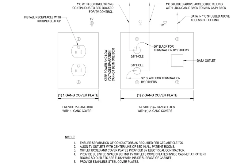
This electrical detail shows a patient room television and data outlet assembly with strict separation requirements between power and low-voltage systems. Power is supplied via a single-gang box with a one-gang cover plate, featuring a duplex receptacle installed with the ground slot up. Data and control cabling run through one-inch conduits stubbed above the accessible ceiling, incorporating RG6 cable back to the main CATV headend and control wiring continuous to the bed docker. Both data and control lines require thirty-six inches of slack for termination by others. A two-gang box with a two-gang cover plate accommodates the data outlet and associated holes, while a UL listed spacer is provided behind cover plates inside cabinetry to maintain a flush finish with the interior surface. Stainless steel cover plates are specified throughout, and all power and low-voltage conductors must remain separated in compliance with CEC Article 725.
1"C WITH CONTROL WIRING CONTINUOUS TO BED DOCKER FOR TV CONTROL. 1"C STUBBED ABOVE ACCESSIBLE CEILING WITH: -RG6 CABLE BACK TO MAIN CATV BACK DATA IN 1"C STUBBED ABOVE ACCESSIBLE CEILING TV TV 36" SLACK FOR TERMINATION BY OTHERS DATA OUTLET 3/8" HOLE 3/8" HOLE 36" SLACK FOR TERMINATION BY OTHERS KEEP POWER AND LOW VOLTAGESEPARATED!!! CANNOT BE IN ONE BOX! INSTALL RECEPTACLE WITH GROUND SLOT UP (1) 1 GANG COVER PLATE (1) 2 GANG COVER PLATE NOTES: 1. ENSURE SEPARATION OF CONDUCTORS AS REQUIRED PER CEC ARTICLE 725. 2. ALIGN TV OUTLETS WITH CENTER LINE OF BED IN ALL PATIENT ROOMS. 3. OUTLET BOXES AND COVER PLATES PROVIDED BY ELECTRICAL CONTRACTOR. 4. PROVIDE UL LISTED SPACER BEHIND TV OUTLETS COVER PLATES INSIDE CABINET AT PATIENT ROOMS SO OUTLETS ARE FLUSH WITH INSIDE SURFACE OF CABINET. 5. PROVIDE STAINLESS STEEL COVER PLATES. PROVIDE 2- GANG BOX WITH 1- GANG COVER PROVIDE (1)2- GANG BOXES WITH (1) 2- GANG COVERS
Members view this detail in full resolution, download the CAD files (SVG, PDF), and can adapt it in the built-in CAD editor — export DXF, DWG, or PDF.
Start membership