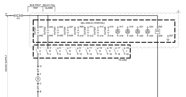
This electrical schematic details a 125Vdc power supply feeding into a partial SEL-3350-A1 controller module. The circuit includes an upstream fuse, bus protection trip and relay fail alarm connections, and an arrangement of digital inputs and outputs labeled A01 through A24. Terminals connect through specific relay contacts and discrete points designated A through J on the TS-3350 terminal strip. Grounding is provided at terminal Z07.
86 -A1 C F B G TS-3350 125VDC SUPPLY P TRIP BUS PROT RELAY FAIL ALARM A02 A01 OUT201 A04 A03 A06 A05 A08 A07 2 1 A 4 3 B 6 5 C 8 7 D 10 9 E 12 11 F 14 13 G 16 15 OUT202 OUT203 OUT204 18 17 I SEL-3350-A1 (PARTIAL) A10 A09 A12 A11 A14 A13 A16 A15 A18 A17 IN 201 A20 A19 IN 202 PS Z06 Z05 Z07 20 19 J FU H A22 A21 IN 203 A24 A23 IN 204 OUT205 OUT206 OUT207 OUT208 2
Members view this detail in full resolution, download the CAD files (SVG, PDF), and can adapt it in the built-in CAD editor — export DXF, DWG, or PDF.
Start membership