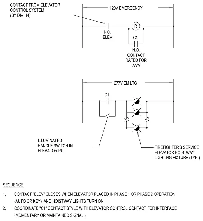
An electrical schematic diagram details the control logic and circuit connections for firefighter's service elevator hoistway lighting. A 120-volt emergency control circuit interfaces with a normally open contact from the elevator control system to energize a relay. A separate 277-volt emergency lighting circuit controls the hoistway lighting fixtures through an illuminated handle switch in the elevator pit and relay contacts. Sequence notes specify that hoistway lights must turn on automatically when the elevator is placed in Phase 1 or Phase 2 operation.
R 120V EMERGENCY 277V EM LTG FIREFIGHTER'S SERVICE ELEVATOR HOISTWAY LIGHTING FIXTURE (TYP.) C1 N.O. CONTACT RATED FOR 277V N.O. ELEV CONTACT FROM ELEVATOR CONTROL SYSTEM (BY DIV. 14) C1 ILLUMINATED HANDLE SWITCH IN ELEVATOR PIT SEQUENCE: 1. CONTACT "ELEV" CLOSES WHEN ELEVATOR PLACED IN PHASE 1 OR PHASE 2 OPERATION (AUTO OR KEY), AND HOISTWAY LIGHTS TURN ON. 2. COORDINATE "C1" CONTACT STYLE WITH ELEVATOR CONTROL CONTACT FOR INTERFACE. (MOMENTARY OR MAINTAINED SIGNAL.)
Members view this detail in full resolution, download the CAD files (SVG, PDF), and can adapt it in the built-in CAD editor — export DXF, DWG, or PDF.
Start membership