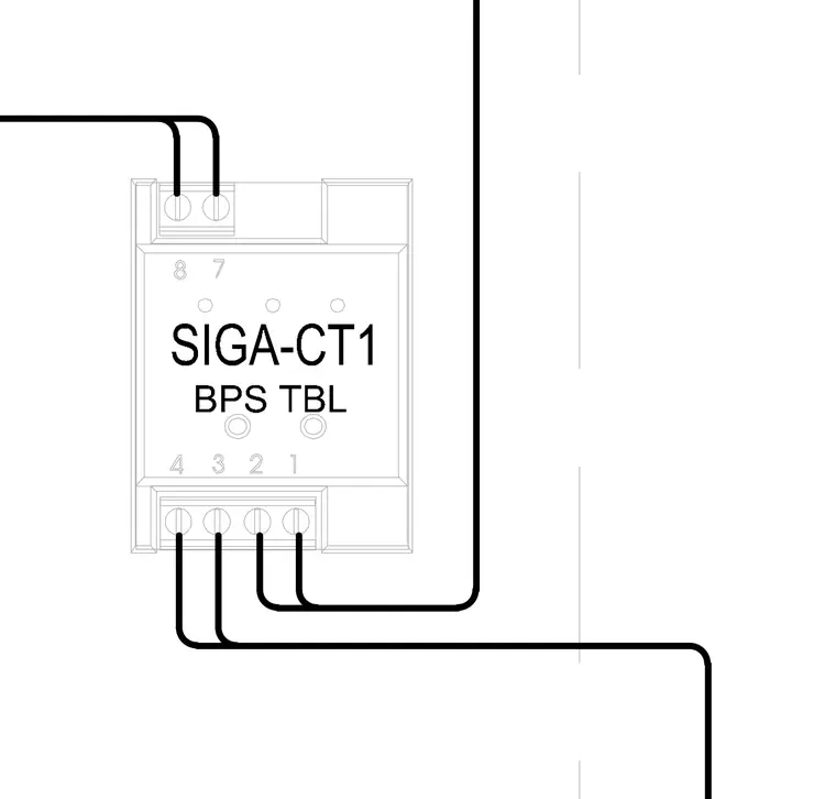
A SIGA-CT1 single input module is wired with external control circuits connecting to numbered terminal blocks. Power supply and trouble inputs are routed through dedicated screw terminals on the device housing. Field wiring conductors terminate at labeled screw terminals 1 through 4 at the base and terminals 7 and 8 at the top.
Members view this detail in full resolution, download the CAD files (SVG, PDF), and can adapt it in the built-in CAD editor — export DXF, DWG, or PDF.
Start membership