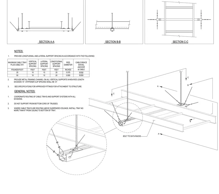
This seismic bracing detail provides lateral and longitudinal support for suspended cable trays using threaded rods, swivel anchors, and cable braces. Vertical support spacing, lateral support spacing, and longitudinal support spacing are determined by the combined cable tray and cable weight per foot. Metal framing channels are installed on vertical supports when rod lengths exceed fourteen inches. Cable trays suspended above ceilings must be positioned no more than six inches from the ceiling to the bottom of the tray.
GENERAL NOTES: NOTES: MAXIMUM CABLE TRAY PLUS CABLE WT. VERTICAL SUPPORT SPACING LATERAL SUPPORT SPACING LONGITUDINAL SUPPORT SPACING ROD DIAMETER CABLE BRACE SWIVEL ANCHOR & CABLE POUNDS/FOOT FEET FEET FEET INCHES 25 10 10 20 0.375 SCB2 50 10 10 20 0.500 SCB3 1. COORDINATE ROUTING OF CABLE TRAYS AND SUPPORT SYSTEMS WITH ALL DIVISIONS. 2. DO NOT SUPPORT FROM BOTTOM CORD OF TRUSSES. 3. WHERE CABLE TRAYS ARE ROUTING ABOVE SUSPENDED CEILINGS, INSTALL TRAY NO MORE THAN 6" FROM CEILING TO BOTTOM OF TRAY. 1. PROVIDE LONGITUDINAL AND LATERAL SUPPORT SPACING IN ACCORDANCE WITH THE FOLLOWING: 2. PROVIDE METAL FRAMING CHANNEL ON ALL VERTICAL SUPPORTS WHEN ROD LENGTH EXCEEDS 14". STIFFENER CLIP SPACING SHALL BE 12". 3. SEE SPECIFICATIONS FOR APPROVED FITTINGS FOR ATTACHMENT TO STRUCTURE. SECTION A-A SECTION B-B SECTION C-C B C B A A C BOLT TO DATA RACKS
Members view this detail in full resolution, download the CAD files (SVG, PDF), and can adapt it in the built-in CAD editor — export DXF, DWG, or PDF.
Start membership