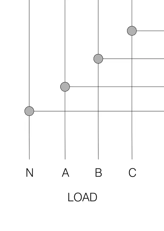
An energy meter wiring diagram maps the neutral and phases A, B, and C for load connections. Vertical lines represent the incoming and outgoing circuit conductors, while circular nodes indicate connection points.
Members view this detail in full resolution, download the CAD files (SVG, PDF), and can adapt it in the built-in CAD editor — export DXF, DWG, or PDF.
Start membership