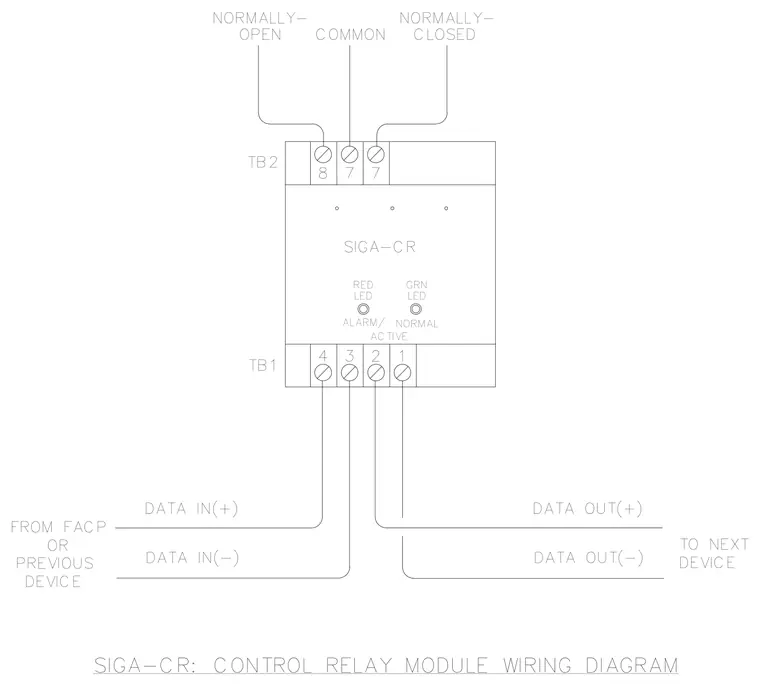
This wiring diagram details the connections for a SIGA-CR control relay module. Terminal block TB1 connects to the fire alarm control panel or previous device via data in positive and negative lines, and continues to the next device through data out positive and negative lines. Terminal block TB2 provides normally open, common, and normally closed relay contact connections. Status indicators include a red LED for alarm or active state and a green LED for normal operation.
NORMALLY- OPEN DEVICE PREVIOUS FROM FACP OR DATA IN(-) DATA IN(+) TB1 TB2 ALARM/ TO NEXT 4 ACTIVE 3 2 NORMAL 1 DATA OUT(-) DEVICE DATA OUT(+) SIGA-CR RED LED 8 7 7 LED GRN NORMALLY- COMMON CLOSED SIGA-CR: CONTROL RELAY MODULE WIRING DIAGRAM
Members view this detail in full resolution, download the CAD files (SVG, PDF), and can adapt it in the built-in CAD editor — export DXF, DWG, or PDF.
Start membership