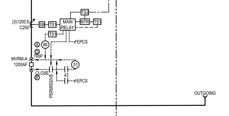
An MVRM-A 1200AF main relay circuit diagram integrates three 1200:5 C200 current transformers with auxiliary contacts and interlocking TS1 and TS2 time switches. The control scheme incorporates device 86 lockout relay functions alongside device 43 selector switches and EPCS telemetry inputs. Trip and close signals route through the permissive outgoing motor feeder configuration.
MVRM-A 1200AF (3)1200:5 C200 SB MAIN RELAY TS1 TRIP CLOSE 01 EPCS 43 86 TS1 EPCS A G R PERMISSIVE OUTGOING MTR TS1 TS2
Members view this detail in full resolution, download the CAD files (SVG, PDF), and can adapt it in the built-in CAD editor — export DXF, DWG, or PDF.
Start membership