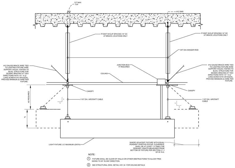
A pendant-mounted light fixture is suspended from an overhead concrete deck using three-eighths-inch diameter hanger rods and one-sixteenth-inch diameter aircraft cables. Seismic bracing is provided by four number twelve gauge brace wires tied to lighting fixture wire support holes and fastened to the building structure in two directions with one-quarter-inch by two-and-one-half-inch long screw eyes. P1000T channels with clips are spaced fourteen inches on center at brace locations only. Canopies conceal the attachment points at the ceiling level, and a junction box is provided as required with number twelve sheet metal screws.
6" AS REQUIRED 1 1 1 1 WHERE ADJACENT FIXTURE WITH EQUAL PENDANT LENGTHS OCCUR, CLEARANCE SHALL BE AT LEAST 1.5 TIMES THE PENDANT LENGTH MEASURED FROM BOTTOM OF FIXTURE PER SECTION 2.1.1 OF IR 16-9. NOTE: FIXTURE SHALL BE CLEAR OF WALLS OR OTHER OBSTRUCTIONS TO ALLOW FREE SWING TO 45° IN ANY DIRECTION. LIGHT FIXTURE (12' MAXIMUM LENTH) CANOPY 1/16" DIA. AIRCRAFT CABLE 1/16" DIA. AIRCRAFT CABLE CANOPY JUNCTION BOX IF REQUIRED #12 SMS TYP 1/2" MAX CEILING 1 SEE STRUCTURAL DWG. DETAIL 4/S1.34 FOR CEILING DETAILS. 2 3/8" DIA HANGER ROD #12 GAUGE BRACE WIRE TIED TO LIGHTING FIXTURE WIRE SUPPORT HOLES, FASTEN TO BLDG. STRUCTURE FOR SEISMIC BRACING AT TWO DIRECTIONS WITH 1/4 " X 2 1_ 2 " LONG SCREW EYE OR EQUAL. PROVIDE MINIMUM (4) WIRE PER FIXTURE. P1000T W/CLIP SPACING 14" OC AT BRACE LOCATIONS ONLY P1000T W/CLIP SPACING 14" OC AT BRACE LOCATIONS ONLY #12 GAUGE BRACE WIRE TIED TO LIGHTING FIXTURE WIRE SUPPORT HOLES, FASTEN TO BLDG. STRUCTURE FOR SEISMIC BRACING AT TWO DIRECTIONS WITH 1/4 " X 2 1_ 2 " LONG SCREW EYE OR EQUAL. PROVIDE MINIMUM (4) WIRE PER FIXTURE.
Members view this detail in full resolution, download the CAD files (SVG, PDF), and can adapt it in the built-in CAD editor — export DXF, DWG, or PDF.
Start membership