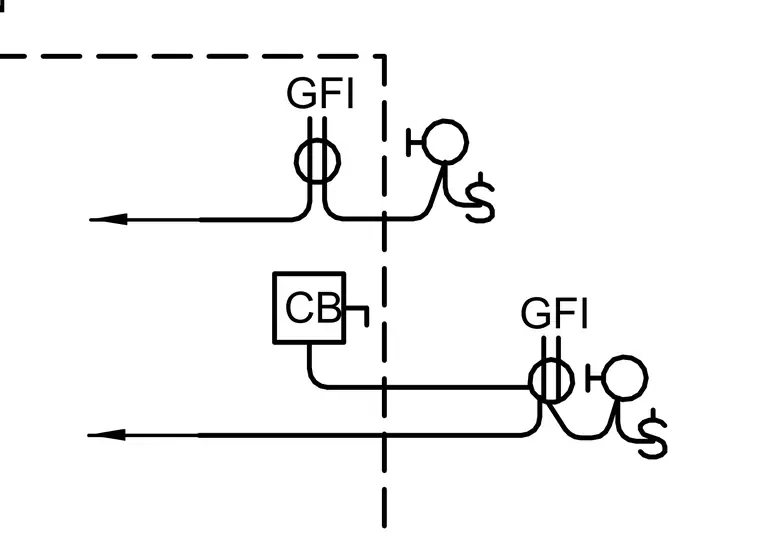
An electrical schematic indicates circuit connections incorporating ground fault interrupter receptacles and a circuit breaker box. Wiring runs connect the components across a designated partition line marked by a dashed border. Directional arrows designate the path of electrical feeds.
Members view this detail in full resolution, download the CAD files (SVG, PDF), and can adapt it in the built-in CAD editor — export DXF, DWG, or PDF.
Start membership