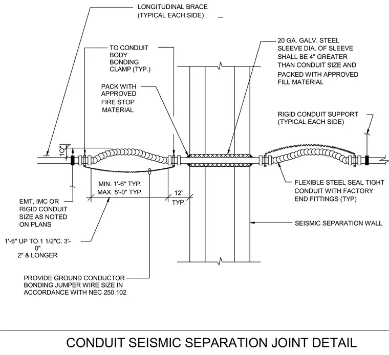
Electrical conduit transitions across a seismic separation wall using a flexible steel seal-tight conduit section fitted with factory end fittings. The wall opening is sleeved with twenty gauge galvanized steel, with the sleeve diameter four inches greater than the conduit size and packed with approved fill material and fire stop material. Rigid conduit supports and longitudinal braces are installed typically on each side, spaced between one foot six inches and five feet depending on conduit size. A ground conductor bonding jumper wire sized per National Electrical Code two hundred fifty point one hundred two connects across the joint via conduit body bonding clamps.
APPROVED FIRE STOP MATERIAL MIN. 1'-6" TYP. MAX. 5'-0" TYP. RIGID CONDUIT ON PLANS SIZE AS NOTED EMT, IMC OR 1O" END FITTINGS (TYP) FLEXIBLE STEEL SEAL TIGHT CONDUIT WITH FACTORY SEISMIC SEPARATION WALL RIGID CONDUIT SUPPORT (TYPICAL EACH SIDE) 12" TYP. LONGITUDINAL BRACE (TYPICAL EACH SIDE) PACK WITH SLEEVE DIA. OF SLEEVE SHALL BE 4" GREATER THAN CONDUIT SIZE AND PACKED WITH APPROVED FILL MATERIAL 20 GA. GALV. STEEL 1'-6" UP TO 1 1/2"C. 3'- 0" 2" & LONGER TO CONDUIT BODY BONDING CLAMP (TYP.) PROVIDE GROUND CONDUCTOR BONDING JUMPER WIRE SIZE IN ACCORDANCE WITH NEC 250.102 CONDUIT SEISMIC SEPARATION JOINT DETAIL
Members view this detail in full resolution, download the CAD files (SVG, PDF), and can adapt it in the built-in CAD editor — export DXF, DWG, or PDF.
Start membership