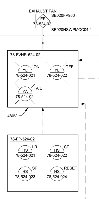
An electrical schematic showing the 480V power distribution and control circuit for exhaust fan SE020FP900 fed from motor control center section SE020NSWPMCC04-1. The system utilizes starter panel 78-FVNR-524-02 containing yellow ON and OFF indicator lights along with a yellow fail indicator light. A separate local control station 78-FP-524-02 houses hand-off-auto selector switches and a reset switch.
HS 78-524-021 LR HS 78-524-022 ST HS 78-524-023 SP HS 78-524-024 RESET )3 EF EXHAUST FAN SE020NSWPMCC04-1 SE020FP900 )915 480V YL 78-524-022 OFF YA FAIL YL 78-524-021 ON
Members view this detail in full resolution, download the CAD files (SVG, PDF), and can adapt it in the built-in CAD editor — export DXF, DWG, or PDF.
Start membership