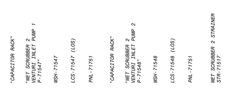
This electrical diagram details the control and power setup for wet scrubber capacitor racks and venturi inlet pumps. The layout coordinates capacitor racks with local control stations, panels, and strainers for pump units P-71547 and P-71548.
WET SCRUBBER 2 STRAINER STR-71517 PNL-71751 LCS-71548 (LOS) PNL-71751 LCS-71547 (LOS) MSH-71547 "WET SCRUBBER 2 VENTURI INLET PUMP 1 P-71547 " CAPACITOR RACK MSH-71548 "WET SCRUBBER 2 VENTURI INLET PUMP 2 P-71548" CAPACITOR RACK
Members view this detail in full resolution, download the CAD files (SVG, PDF), and can adapt it in the built-in CAD editor — export DXF, DWG, or PDF.
Start membership