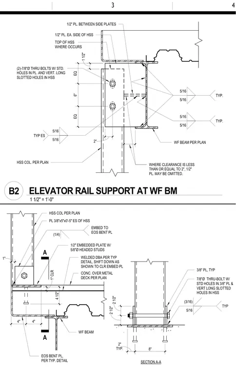
An elevator rail support assembly ties a hollow structural section column to a wide-flange beam and a concrete-filled metal deck. The connection features half-inch plates on each side of the hollow structural section, secured by two seven-eighths-inch diameter through-bolts with standard holes in the plates and vertical long slotted holes in the hollow structural section. Where clearance is less than or equal to two inches, a half-inch plate may be omitted. Fillet welds of five-sixteenths inch are typical throughout the connection joints. An embedded half-inch plate with five-eighths-inch diameter headed studs anchors the assembly into the concrete over the metal deck.
WF BEAM WELDED DBA PER TYP DETAIL, SHIFT DOWN AS SHOWN TO CLR EMBED PL EOS BENT PL, PER TYP. DETAIL (1/4) 4 1/2" 1" CONC. OVER METAL DECK PER PLAN 4" 4" 1/2" EMBEDDED PLATE W/ 5/8"Ø HEADED STUDS TYP. 2" 8" A SECTION A-A 7/8"Ø THRU-BOLT W/ STD HOLES IN 3/8" PL & VERT LONG SLOTTED HOLES IN HSS 5/16 (3/16) TYP PL 3/8"x5"x0'-5" ES OF HSS 2 1/2" 2 1/2" A 1" CLR 3/8" PL, TYP EMBED TO EOS BENT PL HSS COL PER PLAN WF BEAM PER PLAN HSS COL. PER PLAN 1/2" PL. EA. SIDE OF HSS (2)-7/8"Ø THRU BOLTS W/ STD. HOLES IN PL. AND VERT. LONG SLOTTED HOLES IN HSS 5/16 5/16 TYP. EQ 6" EQ TOP OF HSS WHERE OCCURS 1 1/2" . 1/2" PL. BETWEEN SIDE PLATES 5/16 5/16 WHERE CLEARANCE IS LESS THAN OR EQUAL TO 2", 1/2" PL. MAY BE OMITTED. 2" TYP ES 5/16 5/16 TYP. 4 3 1 1/2" = 1'-0" B2 ELEVATOR RAIL SUPPORT AT WF BM
Members view this detail in full resolution, download the CAD files (SVG, PDF), and can adapt it in the built-in CAD editor — export DXF, DWG, or PDF.
Start membership