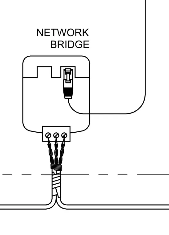
A network bridge unit receives incoming low-voltage cabling secured at a terminal block with three screw connections. A patch cable plugs into the top port of the network bridge to route the signal upward. The enclosure houses the device and organizes the cabling transition across the boundary line.
Members view this detail in full resolution, download the CAD files (SVG, PDF), and can adapt it in the built-in CAD editor — export DXF, DWG, or PDF.
Start membership