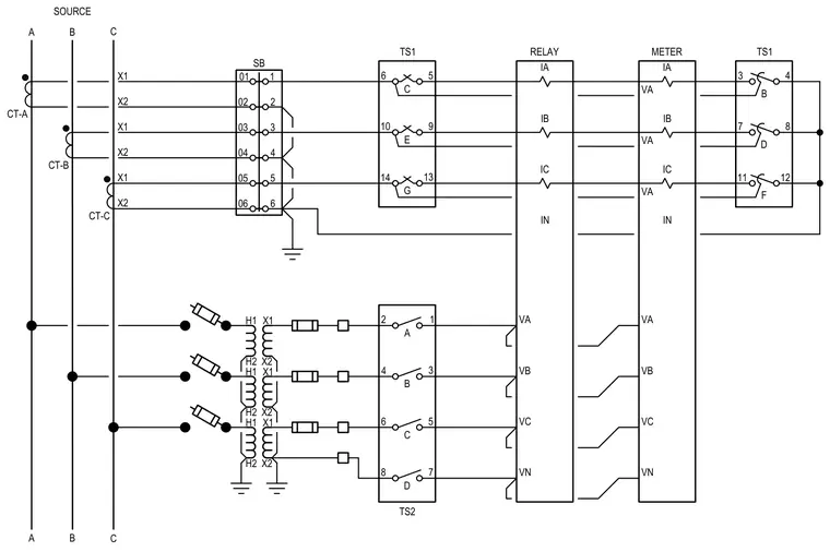
Electrical schematic detailing phase source connections routed through current transformers CT-A, CT-B, and CT-C to shorting blocks, terminal strips, relay inputs, and meters. Secondary circuits incorporate fused potential transformers feeding voltage inputs for phase monitoring and measurement.
A B C 01 SB 1 02 2 03 3 04 4 05 5 06 6 H1 H2 X1 X2 H1 H2 X1 X2 H1 H2 X1 X2 C E G 6 10 14 9 13 5 TS1 B D F 3 7 11 8 12 4 TS1 A B C D 2 4 6 8 3 5 7 1 TS2 RELAY IA IB IC IN VA VB VC VN A B C SOURCE X2 X1 X2 X1 X2 X1 CT-A CT-B CT-C METER IA IB IC IN VA VB VC VN VA VA VA
Members view this detail in full resolution, download the CAD files (SVG, PDF), and can adapt it in the built-in CAD editor — export DXF, DWG, or PDF.
Start membership