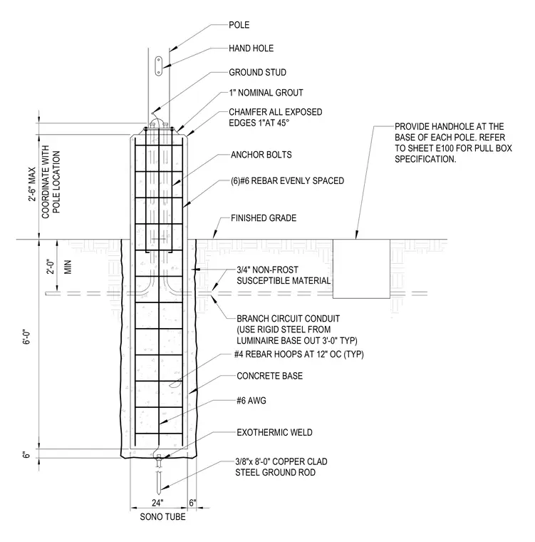
A typical light pole base rests on a six-foot concrete foundation formed with a twenty-four-inch sonotube. The assembly is reinforced vertically with six number six rebar and horizontally with number four rebar hoops spaced at twelve inches on center. Anchor bolts secure the pole to the top of the concrete pier, which features a one-inch nominal grout layer and a one-inch chamfer at forty-five degrees on all exposed edges. A branch circuit conduit enters the base, requiring rigid steel for the first three feet out from the luminaire base, surrounded by three-quarters of an inch of non-frost susceptible material. A three-eighths-inch by eight-foot copper-clad steel ground rod is driven into the bottom of the excavation and connected to the pole via a number six American Wire Gauge wire using an exothermic weld.
POLE HAND HOLE GROUND STUD 1" NOMINAL GROUT CHAMFER ALL EXPOSED EDGES 1"AT 45° ANCHOR BOLTS (6)#6 REBAR EVENLY SPACED FINISHED GRADE PROVIDE HANDHOLE AT THE BASE OF EACH POLE. REFER TO SHEET E100 FOR PULL BOX SPECIFICATION. 3/4" NON-FROST SUSCEPTIBLE MATERIAL BRANCH CIRCUIT CONDUIT (USE RIGID STEEL FROM LUMINAIRE BASE OUT 3'-0" TYP) #4 REBAR HOOPS AT 12" OC (TYP) CONCRETE BASE #6 AWG EXOTHERMIC WELD 3/8"x 8'-0" COPPER CLAD STEEL GROUND ROD 24" 6" SONO TUBE 6" 6'-0" 2'-0" MIN 2'-6" MAX COORDINATE WITH POLE LOCATION
Members view this detail in full resolution, download the CAD files (SVG, PDF), and can adapt it in the built-in CAD editor — export DXF, DWG, or PDF.
Start membership