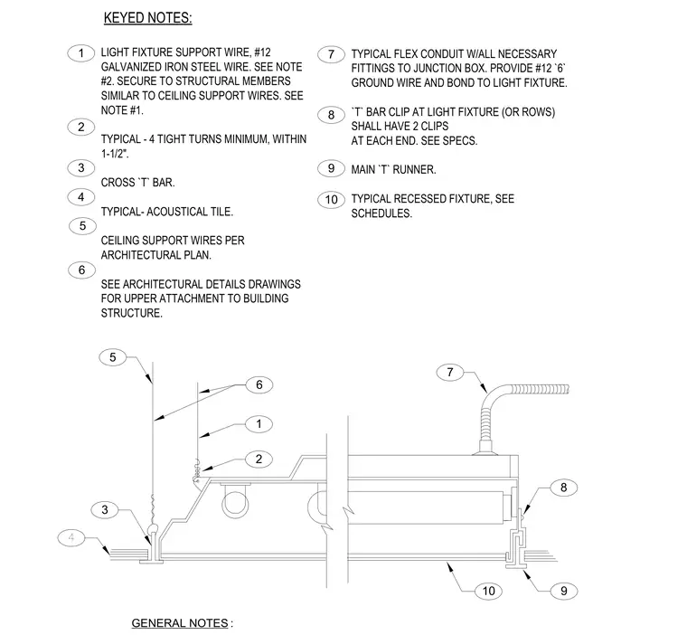
Suspension and electrical connection method for a recessed light fixture installed within an acoustical tile T-bar ceiling system. The fixture is supported independently from the building structure using number 12 galvanized iron steel wire featuring a minimum of four tight turns within 1-1/2 inches. The light fixture rests within the main T-runner and cross T-bar grid, secured by two T-bar clips at each end. Power is supplied via flexible conduit with all necessary fittings connected to a junction box, accompanied by a number 6 ground wire bonded directly to the light fixture. Acoustical tiles finish the ceiling plane flush with the recessed fixture.
KEYED NOTES: LIGHT FIXTURE SUPPORT WIRE, #12 GALVANIZED IRON STEEL WIRE. SEE NOTE #2. SECURE TO STRUCTURAL MEMBERS SIMILAR TO CEILING SUPPORT WIRES. SEE NOTE #1. TYPICAL - 4 TIGHT TURNS MINIMUM, WITHIN 1-1/2". CROSS `T` BAR. TYPICAL- ACOUSTICAL TILE. CEILING SUPPORT WIRES PER ARCHITECTURAL PLAN. SEE ARCHITECTURAL DETAILS DRAWINGS FOR UPPER ATTACHMENT TO BUILDING STRUCTURE. TYPICAL FLEX CONDUIT W/ALL NECESSARY FITTINGS TO JUNCTION BOX. PROVIDE #12 `6` GROUND WIRE AND BOND TO LIGHT FIXTURE. `T` BAR CLIP AT LIGHT FIXTURE (OR ROWS) SHALL HAVE 2 CLIPS AT EACH END. SEE SPECS. MAIN `T` RUNNER. TYPICAL RECESSED FIXTURE, SEE SCHEDULES. 1 7 6 2 5 3 6 5 4 3 2 1 10 9 8 7 9 10 8 GENERAL NOTES : 4
Members view this detail in full resolution, download the CAD files (SVG, PDF), and can adapt it in the built-in CAD editor — export DXF, DWG, or PDF.
Start membership