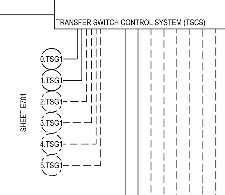
The transfer switch control system and its connection to multiple automatic transfer switch units designated 0.TSG1 through 5.TSG1 are detailed in this diagram. Control lines route from the transfer switch control system module to each individual TSG1 unit as indicated on sheet E701. Dashed and solid lines represent specific control or communication pathways linking the transfer switch group.
3.TSG1 2.TSG1 1.TSG1 0.TSG1 4.TSG1 5.TSG1 TRANSFER SWITCH CONTROL SYSTEM (TSCS) SHEET E701
Members view this detail in full resolution, download the CAD files (SVG, PDF), and can adapt it in the built-in CAD editor — export DXF, DWG, or PDF.
Start membership