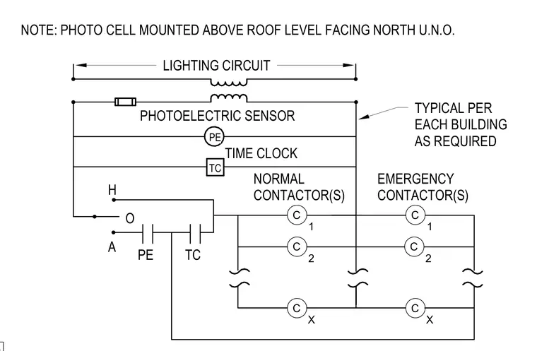
This electrical schematic details the wiring and control logic for lighting circuits utilizing photoelectric sensors and time clocks. Normal and emergency contactors are wired in conjunction with hand-off-auto selector switch logic as required per building. A photoelectric sensor is mounted above the roof level and faces north unless otherwise noted.
TC TIME CLOCK PE PHOTOELECTRIC SENSOR NORMAL CONTACTOR(S) EMERGENCY CONTACTOR(S) TYPICAL PER EACH BUILDING AS REQUIRED LIGHTING CIRCUIT H O A PE TC NOTE: PHOTO CELL MOUNTED ABOVE ROOF LEVEL FACING NORTH U.N.O. C 1 C 2 C X C X C 2 C 1
Members view this detail in full resolution, download the CAD files (SVG, PDF), and can adapt it in the built-in CAD editor — export DXF, DWG, or PDF.
Start membership