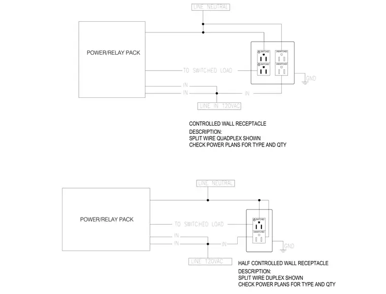
This diagram details the electrical connections between a power and relay pack and controlled wall receptacles operating at 120 volts alternating current. The setup incorporates unswitched and switched lines connected to split-wire duplex and quadplex configurations. Grounding is routed to the receptacle body while neutral and line inputs manage power delivery to switched loads. Power plans should be consulted for specific receptacle types and quantities.
POWER/RELAY PACK POWER/RELAY PACK DESCRIPTION: SPLIT WIRE DUPLEX SHOWN CHECK POWER PLANS FOR TYPE AND QTY DESCRIPTION: SPLIT WIRE QUADPLEX SHOWN CHECK POWER PLANS FOR TYPE AND QTY GND U N S W I T C H E D S W I T C H E D HALF CONTROLLED WALL RECEPTACLE LINE 120VAC TO SWITCHED LOAD LINE NEUTRAL GND S W I T C H E D CONTROLLED WALL RECEPTACLE U N S W I T C H E D U N S W I T C H E D TO SWITCHED LOAD IN IN LINE IN 120VAC IN IN IN IN S W I T C H E D LINE NEUTRAL
Members view this detail in full resolution, download the CAD files (SVG, PDF), and can adapt it in the built-in CAD editor — export DXF, DWG, or PDF.
Start membership