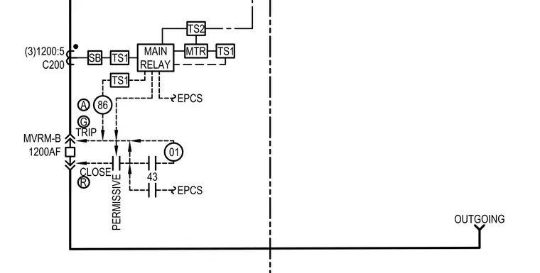
An electrical schematic diagram illustrating a permissive control circuit configuration featuring an MVRM-B 1200AF device connected with three 1200:5 C200 current transformers. The system incorporates a main relay linked to terminal strips TS1 and TS2, a meter MTR, and a lockout relay 86. Control logic includes trip and close paths, a selector switch 43, and EPCS integration. Outgoing connections route through designated terminals for permissive operation.
MVRM-B 1200AF (3)1200:5 C200 SB MAIN RELAY TS1 TRIP CLOSE 01 EPCS 43 86 TS1 EPCS A G R PERMISSIVE OUTGOING MTR TS1 TS2
Members view this detail in full resolution, download the CAD files (SVG, PDF), and can adapt it in the built-in CAD editor — export DXF, DWG, or PDF.
Start membership