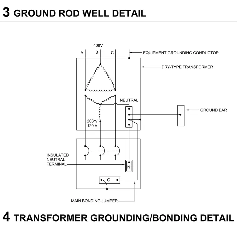
A dry-type transformer diagram shows the electrical grounding and bonding configuration for a 408V primary and 208Y/120V secondary system. The equipment grounding conductor connects to the transformer enclosure. A main bonding jumper links the insulated neutral terminal to the ground bar. Phase conductors A, B, and C feed the transformer windings.
TRANSFORMER GROUNDING/BONDING DETAIL 4 3 GROUND ROD WELL DETAIL N G EQUIPMENT GROUNDING CONDUCTOR DRY-TYPE TRANSFORMER GROUND BAR MAIN BONDING JUMPER INSULATED NEUTRAL TERMINAL NEUTRAL 208Y/ 120 V 408V A B C
Members view this detail in full resolution, download the CAD files (SVG, PDF), and can adapt it in the built-in CAD editor — export DXF, DWG, or PDF.
Start membership