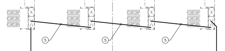
Anchored vertical panels with dashed outlines and designated detail reference markers define the electrical equipment mounting layout. Multiple equipment enclosures are aligned along a common center line with associated interconnection leaders and reference bubbles numbered five. The units are mounted on concrete or structural pads indicated by hatching and boundary lines.
Members view this detail in full resolution, download the CAD files (SVG, PDF), and can adapt it in the built-in CAD editor — export DXF, DWG, or PDF.
Start membership