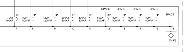
This electrical diagram details switchboard breaker configurations and circuit allocations with specific trip and frame ratings. The layout includes three-pole circuits with ratings ranging from 70 ampere trip and 100 ampere frame up to 1200 ampere trip and 1200 ampere frame, alongside designated spare spaces and a transient voltage surge suppressor connection at position sixteen.
SPACE SPARE SPARE SPARE SPARE TVSS 70AT 100AF 3P 7 1200AT 1200AF 3P 9 1200AT 1200AF 3P 10 800AT 800AF 3P 11 16 1 800AT 800AF 3P 8 800AT 800AF 3P 12 800AT 800AF 3P 13 600AT 600AF 3P 14 400AT 400AF 3P 15
Members view this detail in full resolution, download the CAD files (SVG, PDF), and can adapt it in the built-in CAD editor — export DXF, DWG, or PDF.
Start membership