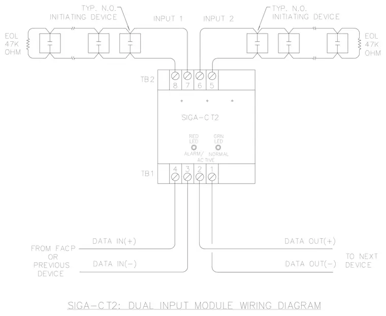
The SIGA-CT2 dual input module connects to data in and data out loops from the fire alarm control panel or previous devices via terminal block 1. Terminal block 2 connects to two separate initiating device circuits containing typical normally open devices terminated with forty-seven kilohm end of line resistors. The module includes red and green LEDs indicating alarm or active and normal states respectively.
INPUT 1 SIGA-CT2: DUAL INPUT MODULE WIRING DIAGRAM DEVICE PREVIOUS FROM FACP OR DATA IN(-) DATA IN(+) 47K EOL OHM TB2 TB1 INITIATING DEVICE TYP. N.O. DATA OUT(+) DATA OUT(-) TO NEXT DEVICE EOL 47K OHM GRN NORMAL SIGA-CT2 3 ACTIVE ALARM/ 4 2 1 LED RED 7 8 6 5 LED INPUT 2 INITIATING DEVICE TYP. N.O.
Members view this detail in full resolution, download the CAD files (SVG, PDF), and can adapt it in the built-in CAD editor — export DXF, DWG, or PDF.
Start membership