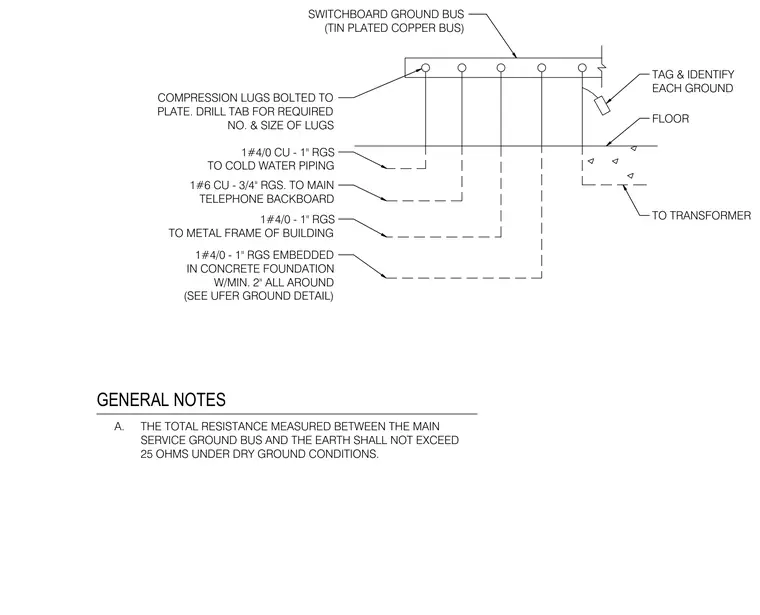
A tin-plated copper switchboard ground bus serves as the central termination point for multiple grounding conductors routed in rigid galvanized steel conduits. Compression lugs bolted to the plate secure a one-aught copper conductor to the cold water piping and a one-number-six copper conductor to the main telephone backboard. Additional one-aught conductors connect to the metal frame of the building and to an embedded concrete foundation electrode with a minimum two-inch concrete encasement. Each ground conductor is tagged and identified, and a separate connection extends to the transformer. The total resistance measured between the main service ground bus and the earth must not exceed twenty-five ohms under dry ground conditions.
GENERAL NOTES A. THE TOTAL RESISTANCE MEASURED BETWEEN THE MAIN SERVICE GROUND BUS AND THE EARTH SHALL NOT EXCEED 25 OHMS UNDER DRY GROUND CONDITIONS. 1#4/0 - 1" RGS TO METAL FRAME OF BUILDING 1#4/0 CU - 1" RGS TO COLD WATER PIPING COMPRESSION LUGS BOLTED TO PLATE. DRILL TAB FOR REQUIRED NO. & SIZE OF LUGS 1#4/0 - 1" RGS EMBEDDED IN CONCRETE FOUNDATION W/MIN. 2" ALL AROUND (SEE UFER GROUND DETAIL) 1#6 CU - 3/4" RGS. TO MAIN TELEPHONE BACKBOARD SWITCHBOARD GROUND BUS (TIN PLATED COPPER BUS) TAG & IDENTIFY EACH GROUND FLOOR TO TRANSFORMER
Members view this detail in full resolution, download the CAD files (SVG, PDF), and can adapt it in the built-in CAD editor — export DXF, DWG, or PDF.
Start membership