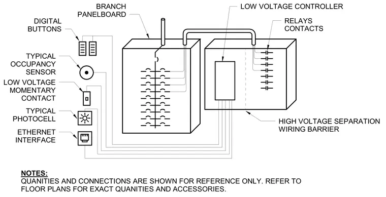
An electrical schematic defining the connection architecture for an exterior lighting control system, featuring a branch panelboard wired to a low voltage controller with integrated relays and contacts. A high voltage separation wiring barrier divides the control enclosure to isolate circuits. External low voltage input devices include digital buttons, a typical occupancy sensor, a low voltage momentary contact, a typical photocell, and an Ethernet interface. Quantities and connections are shown for reference only and must be verified against the architectural floor plans for exact quantities and accessories.
HIGH VOLTAGE SEPARATION WIRING BARRIER RELAYS CONTACTS LOW VOLTAGE CONTROLLER DIGITAL BUTTONS TYPICAL OCCUPANCY SENSOR LOW VOLTAGE MOMENTARY CONTACT TYPICAL PHOTOCELL ETHERNET INTERFACE BRANCH PANELBOARD NOTES: QUANITIES AND CONNECTIONS ARE SHOWN FOR REFERENCE ONLY. REFER TO FLOOR PLANS FOR EXACT QUANITIES AND ACCESSORIES.
Members view this detail in full resolution, download the CAD files (SVG, PDF), and can adapt it in the built-in CAD editor — export DXF, DWG, or PDF.
Start membership