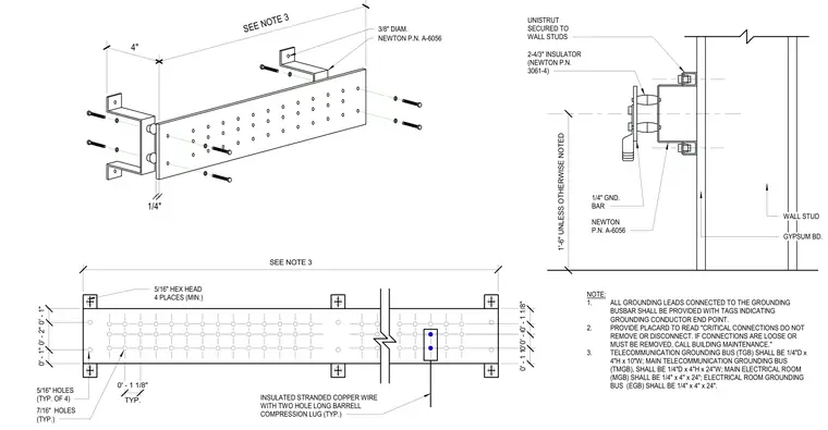
An installation of a grounding bus bar mounted to a wall stud and gypsum board assembly. The copper bus bar is secured using Unistrut channels fastened to the wall studs, with four-inch insulators separating the bar from the mounting surface. Hardware includes three-eighths-inch diameter fasteners, five-sixteenths-inch hex head bolts in four places minimum, and insulated stranded copper wire equipped with two-hole long barrel compression lugs. Specific dimensions and sizing requirements for telecommunication and main electrical room grounding buses are provided in the accompanying notes.
0' - 1" 0' - 2" 0' - 1" TYP. 0' - 1 1/8" 0' - 1 1/8" 0' - 1" 0' - 0 3/4" 0' - 1 1/8" SEE NOTE 3 1/4" 4" 3/8" DIAM. NEWTON P.N. A-6056 5/16" HEX HEAD 4 PLACES (MIN.) 5/16" HOLES (TYP. OF 4) 7/16" HOLES (TYP.) INSULATED STRANDED COPPER WIRE WITH TWO HOLE LONG BARRELL COMPRESSION LUG (TYP.) NOTE: 1. ALL GROUNDING LEADS CONNECTED TO THE GROUNDING BUSBAR SHALL BE PROVIDED WITH TAGS INDICATING GROUNDING CONDUCTOR END POINT. 2. PROVIDE PLACARD TO READ "CRITICAL CONNECTIONS DO NOT REMOVE OR DISCONNECT. IF CONNECTIONS ARE LOOSE OR MUST BE REMOVED, CALL BUILDING MAINTENANCE." 3. TELECOMMUNICATION GROUNDING BUS (TGB) SHALL BE 1/4"D x 4"H x 10"W; MAIN TELECOMMUNICATION GROUNDING BUS (TMGB), SHALL BE 1/4"D x 4"H x 24"W; MAIN ELECTRICAL ROOM (MGB) SHALL BE 1/4" x 4" x 24"; ELECTRICAL ROOM GROUNDING BUS (EGB) SHALL BE 1/4" x 4" x 24". 1'-6" UNLESS OTHERWISE NOTED NEWTON P.N. A-6056 1/4" GND. BAR WALL STUD GYPSUM BD. UNISTRUT SECURED TO WALL STUDS 2-4/3" INSULATOR (NEWTON P.N. 3061-4) SEE NOTE 3
Members view this detail in full resolution, download the CAD files (SVG, PDF), and can adapt it in the built-in CAD editor — export DXF, DWG, or PDF.
Start membership