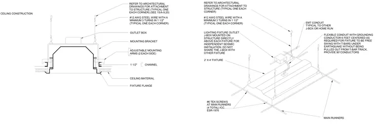
A recessed lighting fixture is secured within the ceiling material using adjustable mounting arms on each side tied to one and one-half inch main runner channels. The lighting fixture outlet junction box is mounted directly on the structure above the fixture for independent seismic installation, utilizing number twelve gauge steel wire with a minimum of three turns in one and one-half inches at each corner. Flexible conduit with a grounding conductor, six feet centered, allows the fixture to swing freely during seismic activity without pulling out from the track. Electrical connection continues via electrical metallic tubing conduit to another junction box or home run. Number six TEK screws fasten four total connections at the main runners per evaluation report ICC ESR-1976.
#12 AWG STEEL WIRE WITH A MINIMUM 3 TURNS IN 1 1/2" (TYPICAL ONE EACH CORNER) OUTLET BOX MOUNTING BRACKET REFER TO ARCHITECTURAL DRAWINGS FOR ATTACHMENT TO STRUCTURE (TYPICAL ONE EACH CORNER) (SEE 15/A-9.20) REFER TO ARCHITECTURAL DRAWINGS FOR ATTACHMENT TO STRUCTURE (TYPICAL ONE EACH CORNER) #12 AWG STEEL WIRE WITH A MINIMUM 3 TURNS IN 1 1/2" (TYPICAL ONE EACH CORNER) LIGHTING FIXTURE OUTLET J-BOX MOUNTED ON STRUCTURE DIRECTLY ABOVE EACH FIXTURE FOR INDEPENDENT SEISMIC INSTALATION. DO NOT SHARE THE J-BOX WITH OTHER FIXTURE FLEXIBLE CONDUIT WITH GROUNDING CONDUCTOR 6 FEET CENTERED AS REQUIRED FOR FIXTURE TO BE FREE SWING WITH T-BARS UNDER EARTHQUAKE WITHOUT BEING PULLED OUT FROM T-BAR TRACK. PROVIDE 90°CONDUCTORS EMT CONDUIT TYPICAL TO OTHER J-BOX OR HOME RUN REFER TO A9.20 & A9.21 FOR ADDITIONAL INFORMATION ON CEILING CONSTRUCTION CEILING MATERIAL FIXTURE FLANGE ADJUSTABLE MOUNTING ARMS (2 EACH SIDE) CHANNEL 1 1/2" MAIN RUNNERS 2' X 4' FIXTURE #6 TEX SCREWS AT MAIN RUNNERS (4 TOTAL) ICC ESR-1976
Members view this detail in full resolution, download the CAD files (SVG, PDF), and can adapt it in the built-in CAD editor — export DXF, DWG, or PDF.
Start membership