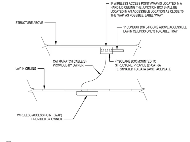
A wireless access point is mounted on the lay-in ceiling tile and connected via owner-provided Category 6A patch cables to a 4-inch square junction box secured to the overhead structure. Two Category 6A cables terminate at a data jack faceplate. A 1-inch conduit or J-hooks route cabling from the junction box to the cable tray depending on ceiling accessibility. For hard lid ceilings, the junction box must be placed in an accessible location nearby and labeled WAP.
STRUCTURE ABOVE LAY-IN CEILING CAT 6A PATCH CABLE(S) PROVIDED BY OWNER 4" SQUARE BOX MOUNTED TO STRUCTURE. PROVIDE (2) CAT 6A TERMINATED TO DATA JACK FACEPLATE WIRELESS ACCESS POINT (WAP) PROVIDED BY OWNER 1" CONDUIT (OR J-HOOKS ABOVE ACCESSIBLE LAY-IN CEILINGS ONLY) TO CABLE TRAY IF WIRELESS ACCESS POINT (WAP) IS LOCATED IN A HARD LID CEILING THE JUNCTION BOX SHALL BE LOCATED IN AN ACCESSIBLE LOCATION AS CLOSE T0 THE 'WAP' AS POSSIBLE. LABEL "WAP".
Members view this detail in full resolution, download the CAD files (SVG, PDF), and can adapt it in the built-in CAD editor — export DXF, DWG, or PDF.
Start membership