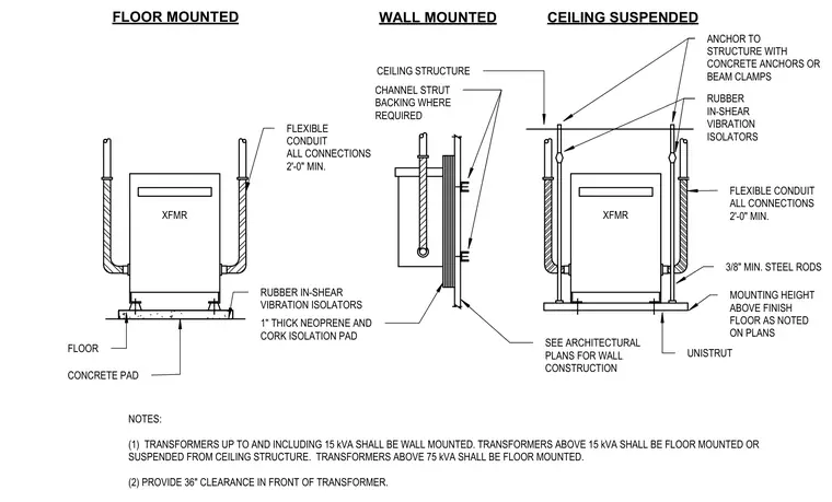
Floor-mounted transformers sit atop a concrete pad over a one-inch-thick neoprene and cork isolation pad with rubber in-shear vibration isolators and flexible conduit connections measuring at least two feet long. Wall-mounted units attach to channel strut backing with rubber in-shear vibration isolators and coordinate with wall construction shown on architectural plans. Ceiling-suspended transformers hang from the ceiling structure using three-eighths-inch minimum steel rods anchored with concrete anchors or beam clamps, utilizing unistrut channels and rubber in-shear vibration isolators. Flexible conduit with a minimum two-foot length connects to all units. Transformers up to and including fifteen kilovolt-amperes are wall-mounted, units above fifteen kilovolt-amperes are floor-mounted or suspended, and units exceeding seventy-five kilovolt-amperes are strictly floor-mounted. A thirty-inch clearance is required in front of every transformer.
CEILING STRUCTURE SEE ARCHITECTURAL PLANS FOR WALL CONSTRUCTION 3/8" MIN. STEEL RODS CHANNEL STRUT BACKING WHERE REQUIRED 1" THICK NEOPRENE AND CORK ISOLATION PAD WALL MOUNTED RUBBER IN-SHEAR VIBRATION ISOLATORS FLEXIBLE CONDUIT ALL CONNECTIONS 2'-0" MIN. ANCHOR TO STRUCTURE WITH CONCRETE ANCHORS OR BEAM CLAMPS CEILING SUSPENDED MOUNTING HEIGHT ABOVE FINISH FLOOR AS NOTED ON PLANS UNISTRUT XFMR RUBBER IN-SHEAR VIBRATION ISOLATORS FLEXIBLE CONDUIT ALL CONNECTIONS 2'-0" MIN. FLOOR FLOOR MOUNTED XFMR NOTES: (1) TRANSFORMERS UP TO AND INCLUDING 15 kVA SHALL BE WALL MOUNTED. TRANSFORMERS ABOVE 15 kVA SHALL BE FLOOR MOUNTED OR SUSPENDED FROM CEILING STRUCTURE. TRANSFORMERS ABOVE 75 kVA SHALL BE FLOOR MOUNTED. (2) PROVIDE 36" CLEARANCE IN FRONT OF TRANSFORMER. CONCRETE PAD
Members view this detail in full resolution, download the CAD files (SVG, PDF), and can adapt it in the built-in CAD editor — export DXF, DWG, or PDF.
Start membership